
4 posts tagged with "import"

View All Tags

Mermaid in draw.io updated to support ELK layout

· 6 min read
draw.io
draw.io Team

Mermaid is a text-based syntax that you can use to describe a diagram, and automatically lay it out neatly on the diagram canvas. Enter your Mermaid diagram description in draw.io via Arrange > Insert > Mermaid in the draw.io menu or + > Mermaid from the toolbar. draw.io has updated to Mermaid version 10.9.1 to support the new ELK automatic layout.
Tell the Mermaid diagram generation tool to use the ELK layout option in your text diagram description

Text to diagram tools in draw.io

There are several text-to-diagram tools built into draw.io:

Paste the Mermaid syntax text version of your diagram and Insert it onto the draw.io canvas An example Gantt chart inserted from Mermaid code
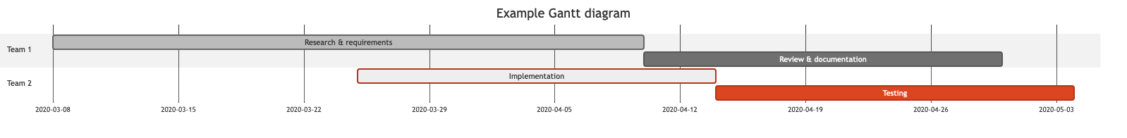
Example Gantt chart generated from Mermaid syntax

Some of these text-to-diagram features generate a diagram as an image on the drawing canvas, and some use draw.io shapes to automatically layout your diagram and let you continue adding draw.io shapes and connectors to it.

You can choose your preferred output when you generate a diagram from Mermaid syntax, although some diagram types - like the Gantt chart above - will only generate to an image.

Insert a Mermaid diagram in draw.io

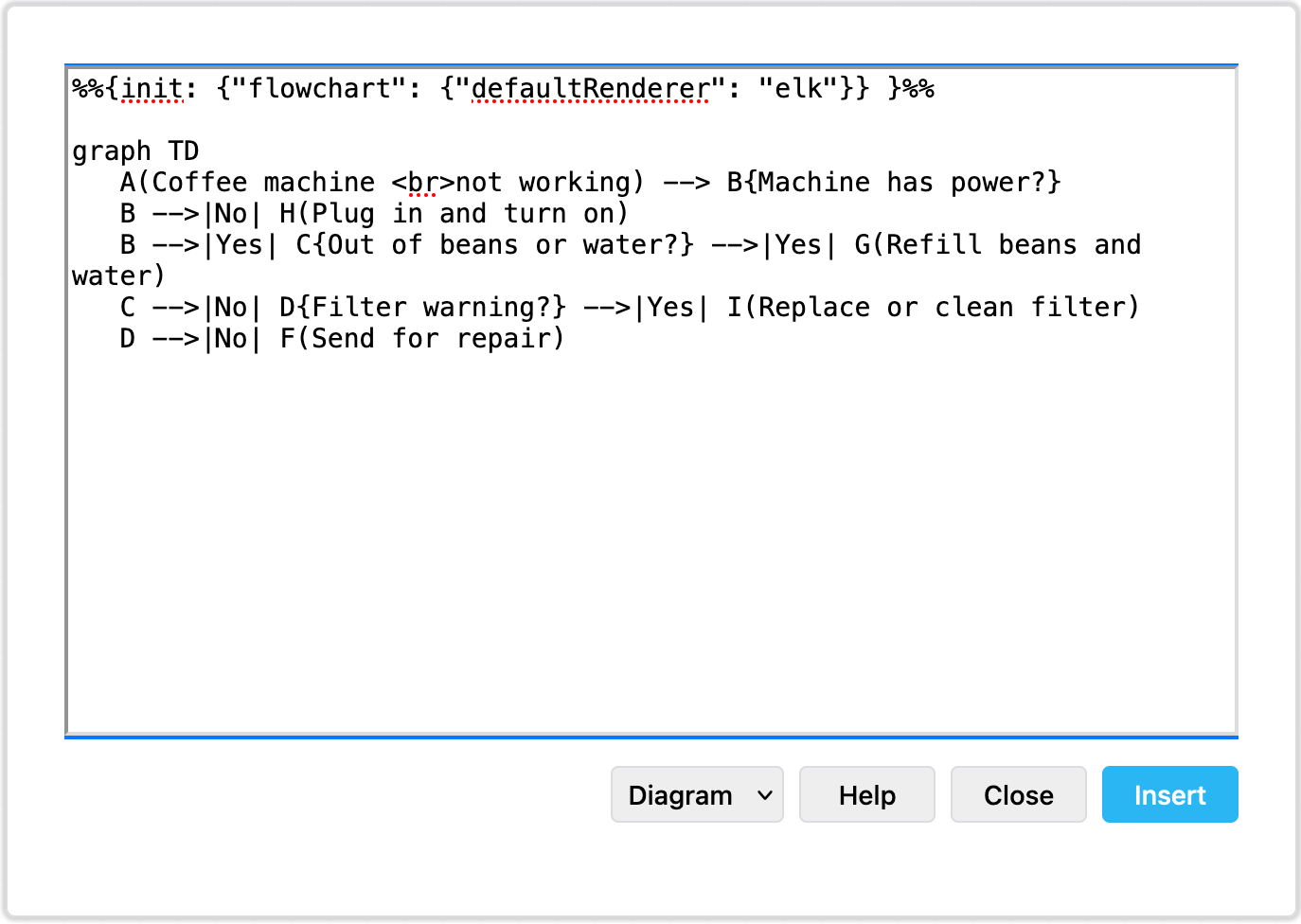
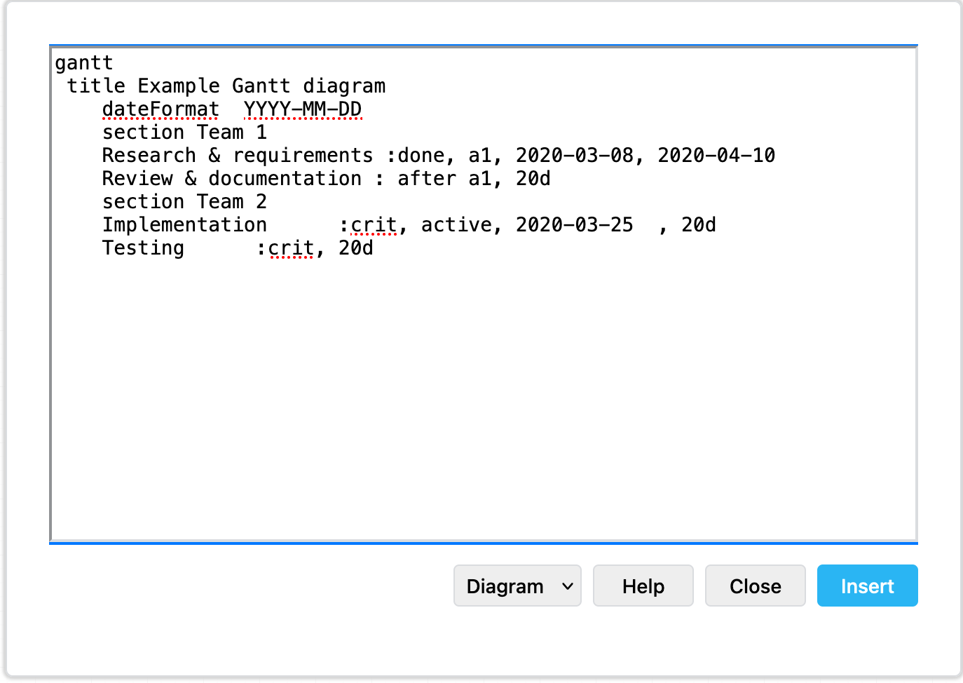
An example coffee machine debugging flow is described in Mermaid syntax below.

graph TD
A(Coffee machine <br />not working) --> B{Machine has power?}
B -->|No| H(Plug in and turn on)
B -->|Yes| C{Out of beans or water?} -->|Yes| G(Refill beans and water)
C -->|No| D{Filter warning?} -->|Yes| I(Replace or clean filter)
D -->|No| F(Send for repair)

Add this Mermaid diagram to draw.io.

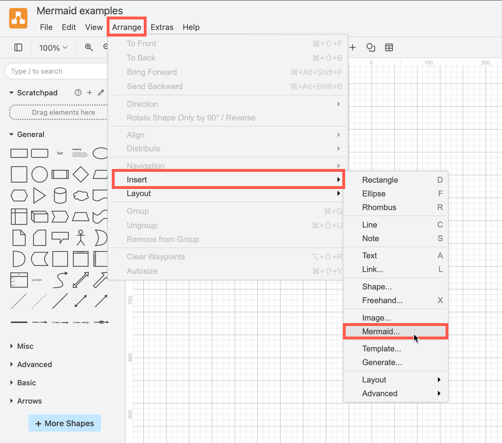
  1. Select Arrange > Insert > Mermaid from the menu or + > Mermaid from the toolbar if you are using the Simple mode or the Sketch editor theme.
    Click Arrange /> Insert > Mermaid to create a diagram from Mermaid Markdown-inspired code
  2. Enter the text description of your diagram using Mermaid syntax in the large text box.
  3. From the drop-down list, select whether you want to insert the diagram with draw.io shapes (Diagram), or as a single image (Image), and click Insert.
    Paste the text in Mermaid syntax, then click Insert

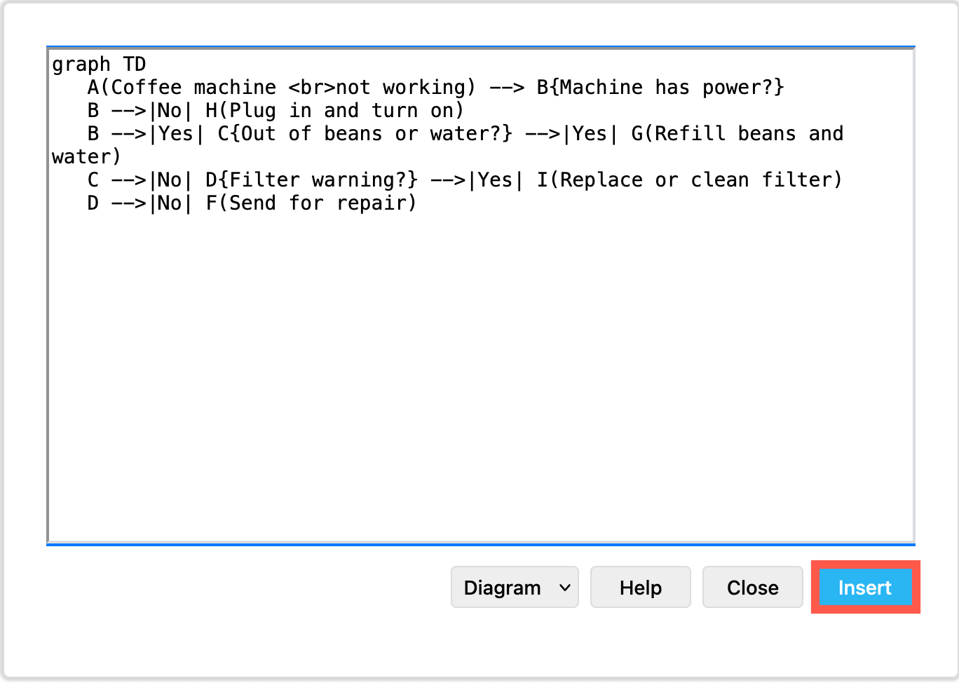
Diagram (default): When you insert the Mermaid diagram using the draw.io shapes, you can connect additional shapes and connectors and style your diagram. To change the original Mermaid syntax, first delete the previously inserted shapes, and re-enter the Mermaid description of your diagram by repeating the steps above.
By default, Mermaid diagrams are added to the drawing canvas with draw.io shapes so you can style and add to your diagram as needed

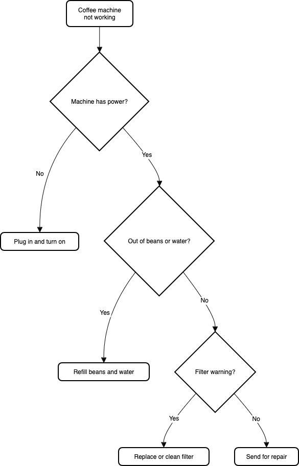
Image: To generate the Mermaid diagram as a single SVG image on the drawing canvas instead, select Image from the drop-down list before you Insert. If you hover over the SVG image, the Mermaid syntax is visible in the tooltip. Note that you can't edit or style the individual shapes or connectors in this SVG image version.
Hover over a Mermaid diagram image in draw.io to see the Mermaid syntax for that diagram in a tooltip

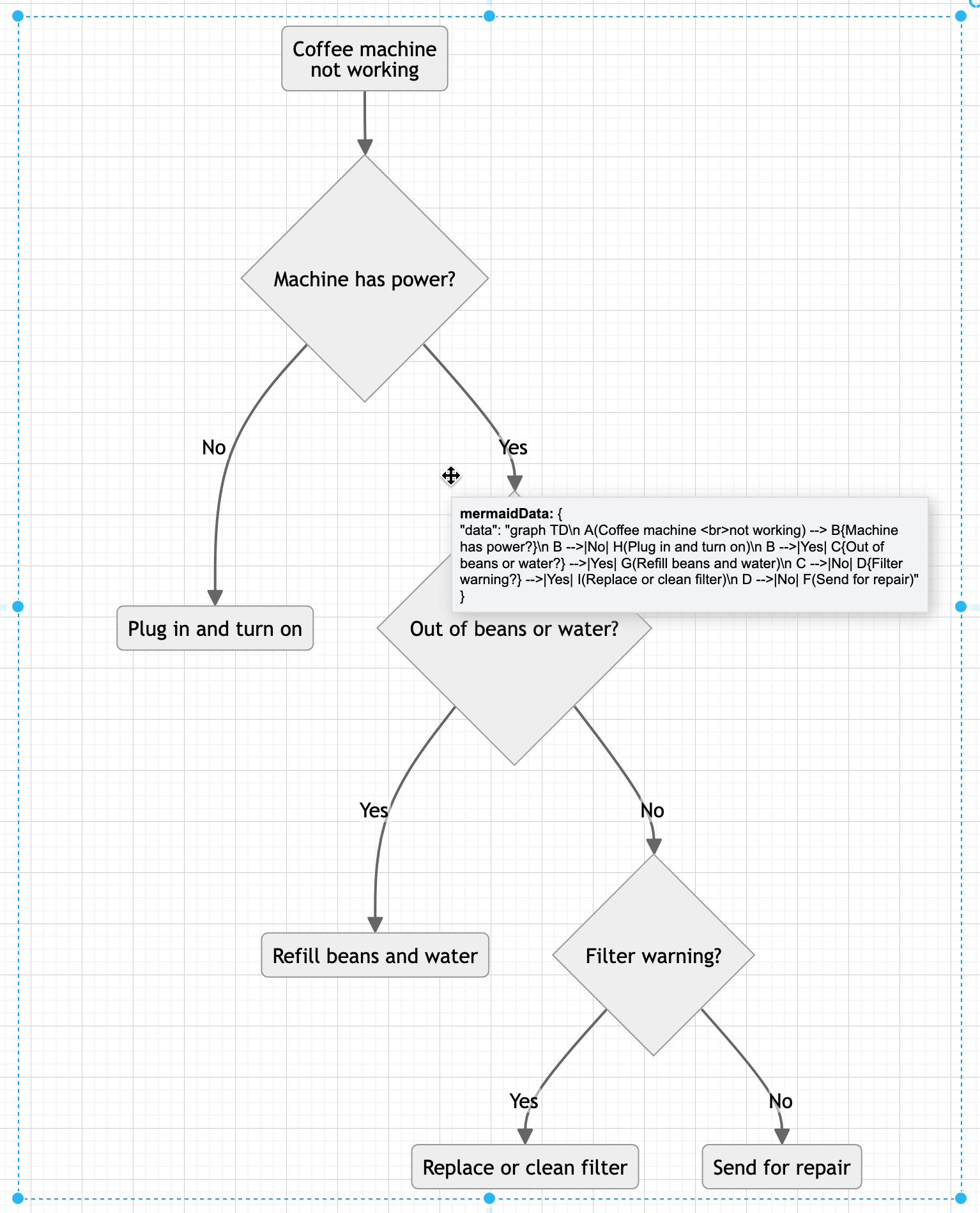
To change a Mermaid diagram added as an image, double click on the SVG on the drawing canvas and edit the Mermaid syntax to regenerate the image.

Please refer to the Mermaid documentation for the complete syntax and styling options.

New ELK layouts for large flowcharts

The new ELK layout option, introduced in Mermaid version 9.4, can generate compacter versions of large and complex flowcharts.

Add the following renderer directive to the top your Mermaid diagram text description:

%%{init: {"flowchart": {"defaultRenderer": "elk"}} }%%

For example, to layout the example Mermaid graph shown above with the ELK renderer command, the insert Mermaid dialog looks as follows.
Tell the Mermaid diagram generation tool to use the ELK layout option in your text diagram description

Click Insert, and the Mermaid diagram will be generated ad drawn with draw.io shapes.
The ELK layout may be more suited for larger and more complex flows

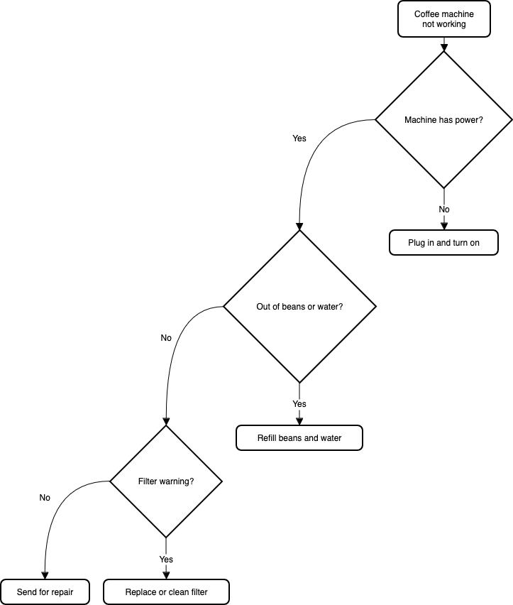
While this example is small and simple, larger flows with complex decisions and many branches may be displayed better using this ELK renderer option.

Note: As this is an experimental feature from the Mermaid developers, it currently only supports the flowchart layout.

Large Mermaid flowchart with and without ELK

Below, one of the more complex draw.io flowchart templates has described in text using Mermaid syntax and inserted as an image. The more compact version on the left used the new ELK renderer directive, and the one on the right did not.

The ELK layout may be more suited for larger and more complex flows

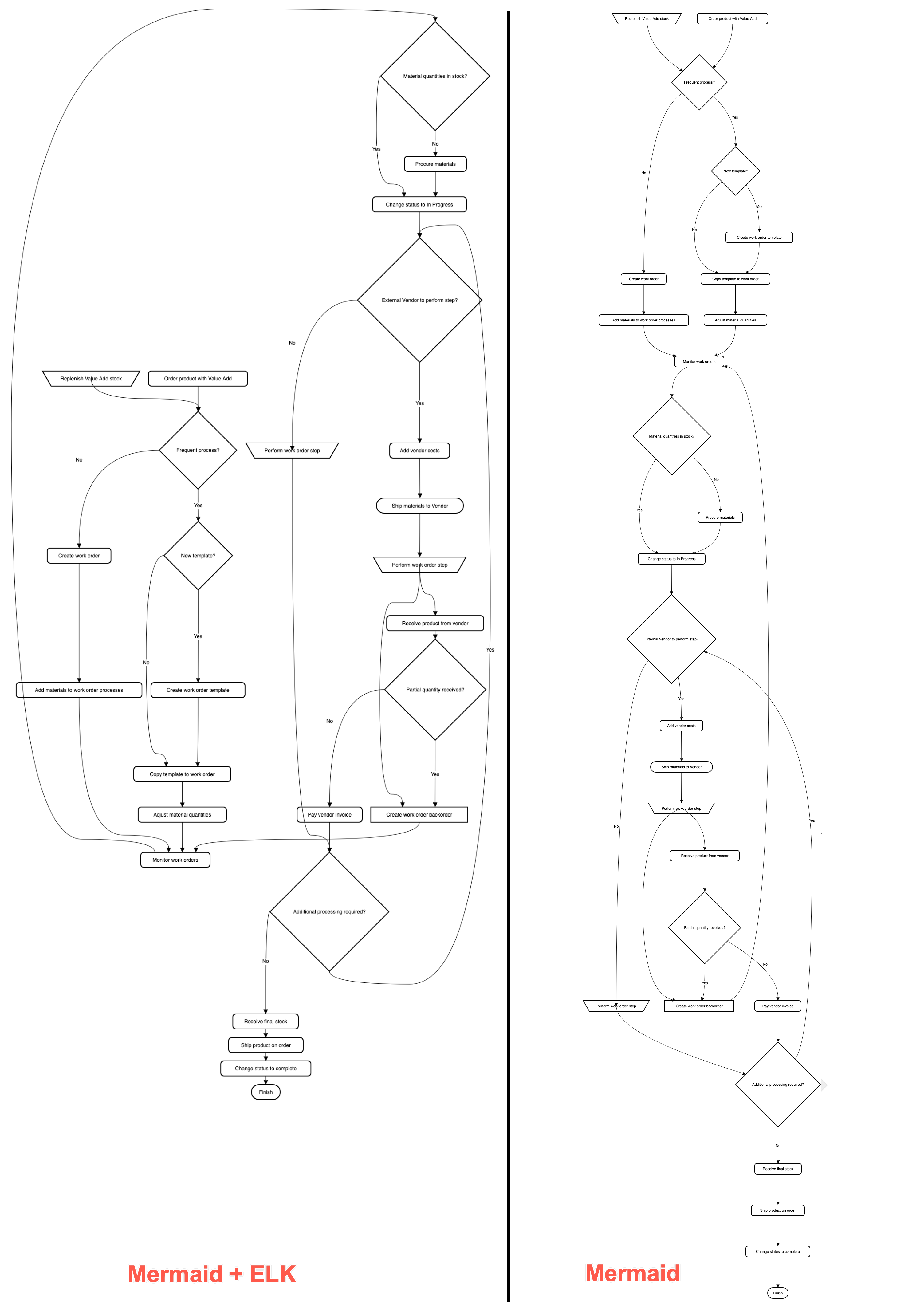
With the ELK renderer directive, the Mermaid code for this flowchart looks as follows.

%%{init: {"flowchart": {"defaultRenderer": "elk"}} }%%

graph TD
A[\Replenish Value Add stock/] --->C
B(Order product with Value Add) --->C
C{Frequent process?} --->|Yes|D
C --->|No|F
D{New template?} --->|Yes|E
D --->|No|G
E(Create work order template) --->G
F(Create work order) --->H
G(Copy template to work order) --->I
H(Add materials to work order processes) --->J
I(Adjust material quantities) --->J
J(Monitor work orders) --->K
K{Material quantities in stock?} --->|No|L
K --->|Yes|M
L(Procure materials) --->M
M(Change status to In Progress) --->N
N{External Vendor to perform step?} --->|Yes|O
N --->|No|P
O(Add vendor costs) --->Q
P[\Perform work order step/] --->R
Q([Ship materials to Vendor]) --->S --->X
R{Additional processing required?} --->|Yes|N
R--->|No|T
S[\Perform work order step/] --->U
T(Receive final stock) --->V
U(Receive product from vendor) --->W
V(Ship product on order) --->Y
W{Partial quantity received?} --->|Yes|X
W --->|No|Z
X[Create work order backorder] ---> J
Y(Change status to complete) --->AA
Z(Pay vendor invoice) --->R
AA([Finish])

Create data-driven diagrams with draw.io

· 8 min read
draw.io
draw.io Team

Using diagrams.net or draw.io together with scripts and data sources, you can create data-driven diagrams, with colours, shapes, text labels and even animations that change to reflect live data.
Update shapes in a diagram based on live data with draw.io, Grafana and the Flowcharting plugin

Aside from live diagrams of cloud network infrastructures, and charts that visualise data in graphs, there are few true data-driven diagrams. As draw.io does not include spreadsheet or graph functionality - it's a diagram editor - dynamically updated charts are not possible.

You can program your own scripts or use integrations with other applications to achieve data-driven diagrams where diagram shapes change to reflect live data because draw.io is open source and the .drawio diagram format uses accessible XML.

How it works

Each shape in a draw.io diagram has a unique shape ID.

Because the diagram data is stored in your file using XML tags, you can use a script to search for the shape ID in the XML source and replace common shape properties with a different value to reflect the data at that time.

What you'll need

  • diagram created in the draw.io editor and saved as an XML file
  • application or script to do the following:
    • display and refresh the diagram
    • query or read the live data
    • analyse the data values and update the shape properties in the diagram according to programmed rules

Example - factory status floorplan

To show you how to build such a data-driven diagram, we'll use an example of a dashboard that shows the status of a machine on a factory floorplan based on real-time sensor data from that machine.

This example uses Grafana and Arnaud Genty's Flowcharting plugin to feed the real-time sensor data recorded in a database to scripts that update the shapes in the diagram based on rules that we define.


Draw your diagram and set it up for data

Create your diagram in draw.io online or one of our draw.io apps.

You can draw any type of diagram - flow charts, wireframes, floorplans, org charts, wiring diagrams, etc.

Avoid using complex shapes for elements you want to update. Those that contain multiple fields, like tables, entity shapes or swimlanes won't typically have unique IDs that you can refer to later.

In this example, we've created a factory floorplan with simple text shapes to show important machine information.
Draw your diagram in draw.io

Set custom unique shape IDs

For each shape that will dynamically update based on a data source, you should override the auto-assigned shape ID to make it easier to refer to later.

  1. Right-click on a shape and select Edit Data. Alternatively, select a shape and press Ctrl+M or Cmd+M.
  2. Hold down Shift and double click on the ID string at the top.
  3. Change the shape ID to something more memorable - make sure it is unique.
  4. Click Apply to save the new shape ID, then click Apply to save the shape data.
    Give each element in your diagram that you want to dynamically update a new, memorable and unique shape ID via its shape data - select a shape and press Ctrl+M

In our example, all of the text shapes that say Text are to be updated. Each has been assigned a new custom unique shape ID.

View the shape IDs in the Properties section on the Style tab.
Check each shape has a unique ID assigned in the Properties section of the Style tab in the format panel

Export your diagram as an XML file

You need to read (and copy) the full XML source of your diagram, so export it as an XML file so it can be easily opened by a text editor.

  1. Select File > Export As > XML from the menu.
  2. Save the file to your local device.

Create a dynamic dashboard

  1. Install Grafana and the Flowcharting plugin.
  2. Configure one or more data sources in Grafana.
  3. Create a new dashboard and add a Flowcharting panel.
    Install Grafana, connect a database and create a dashboard with the Flowcharting plugin - you can add the .drawio diagram in the next step

Add the diagram to the dashboard

  1. Open the diagram .xml file you previously saved in a text editor.
  2. Copy all the diagram data that appears after the initial <?xml ... > tag.
    Open the .xml file in a text editor and copy all of the text that appears after the first XML tag
  3. Now, add the diagram data to the Flowchart panel in Grafana.
  • Set the Editor URL & Theme to our online service at embed.diagrams.net, and select Dark or Light from the drop down list. If you run your own draw.io server, use its URL instead.
  • Set the Source Type to XML.
  • In the Source Content text field, paste the diagram data you copied from your text editor.
    Add the diagram data to the Flowchart panel in Grafana

The diagram will appear in the dashboard preview panel.

Map diagram shape IDs to data queries with rules

Now, you need to link the diagram shapes you want to update, with queries of a data source and rules defined in the Flowchart panel.
Map the diagram shapes you want to dynamically update to data using rules in the Flowchart panel in Grafana

  1. Write the queries to extract the data you need from your data sources. Set the name of the metric to the diagram shape ID that it updates so it's easier to see which query updates which shape.
    Update the name of each metric to match the diagram shape ID that it updates for ease of understanding
  2. Set the behaviour in the Mapping section for each query.
    • Set Identify by to ID as that is how we identify a specific shape.
    • Enable Regular expression and add some rules. In the What field of the rule, enter the specific shape ID for the shape you want to update.
      Set up the rules for each of the shapes you want to update based on data query values
      The shape label is Active or Stop based on the latest database value.

Refer to the Flowcharting mapping documentation if you need help with this step.

You can change the colour or tooltip of the shape, its text label or link, or add an animation.

Now, when your dashboard runs and your data queries are updated, your diagram will update according to the rules you have set.

Update shapes in a diagram based on live data with draw.io, Grafana and the Flowcharting plugin

More data-driven diagram examples

  1. Select one of these live examples of diagrams in the Flowcharting plugin.
  2. Expand the title and select Edit to see how it is set up.
    Have a look at a live example of a draw.io diagram used with the Flowcharting Grafana plugin

Import diagrams from Gliffy Online to draw.io

· 2 min read
draw.io
draw.io Team

Gliffy recently removed their free tier offering in their online version. This means if your trial version has expired, you will no longer be able to edit up to 5 diagrams that you have created, unless you start a paid subscription.

You can use our draw.io online editor to create an unlimited number of diagrams for free, without restrictions. Additionally, you can import your Gliffy diagrams.

How to import Gliffy diagrams

Prior to the removal of the free tier, 1st December 2021, open each diagram in turn in the Gliffy editor. Right click on the editor canvas and select "View diagram source"

The right-click menu in the Gliffy editor, with the view diagram source option selected

In the dialog that appears select the whole text and copy it.

The data model display dialog in Gliffy, showing the data representing the diagram

Open any text editor on your computer and paste the text in. Then save the file, using a .gliffy suffix to end the filename.

Repeat that until you have a file for each Gliffy diagram.

Next, go to app.diagrams.net and drag and drop the first file into the draw.io editor. Your diagram will be imported and you can click on the orange "unsaved diagram" warning to pick your save location.

The save option dialog in draw.io. At the top is a text field to type in the file name. Below are various storage options to select.

You can choose to save back to your computer or to one of the cloud storage options, Google Drive, OneDrive, Dropbox, GitHub or Gitlab.

If you're worried about trusting SaaS vendors with your data, when they can change usage terms at any time, use the draw.io desktop app. Note that the offline application cannot import Gliffy files, but once imported using our online app, you can open, edit and save your files in draw.io Desktop without limitations for free.

Use Cloudcraft to export your AWS architecture to a .drawio diagram

· 4 min read
draw.io
draw.io Team

Using Cloudcraft, you can securely connect to cloud environments and infrastructure components via your architecture diagrams where statistics, resource information and more is updated in real time. The 3D isometric view that Cloudcraft uses is familiar to engineers and IT staff as it often matches the tools they learned on. The automatic updates driven from your company's live systems makes Cloudcraft a fantastic tool for monitoring your AWS cloud infrastructure. The statistics are also helpful to estimate costs when you want to make changes to your system.
Examples of Cloudcraft infrastructure diagrams exported to draw.io

Get started with your AWS infrastructure using the Amazon Architecture Center's training section and the reference architectures.

AWS architecture documentation also needs to be static

To document how your AWS infrastructure changes over time, you need snapshots - diagrams before and after you make changes. You can't use a live system to document what happened in the past. This is especially important to comply with audit and security standards, and to show progress on your IT infrastructure projects.

Export the various stages of your AWS infrastructure's development into static diagrams. You can easily share these diagrams, open and edit them in draw.io, incorporate them into official documentation and reports, and store them in your revision control system to ensure compliance and painless audits.

Cloudcraft makes it easy to export to draw.io.

How to export from Cloudcraft

Note: Please allow pop-ups in your browser.

In your Cloudcraft account, in the top right of the drawing area, click Export > 2D export to draw.io

Export AWS infrastructure from Cloudcraft

The draw.io version of your AWS architecture will open in a new tab in your browser. You can now save this diagram file to your version control system, cloud storage platform, or whichever location you have chosen to maintain a record of your infrastructure.

Exported 2D IoT AWS infrastructure from Cloudcraft into draw.io

When exporting to draw.io, Cloudcraft may not use the most recent AWS shapes in your diagram, but it's easy to update your diagram to the newest AWS shapes yourself.

Editing AWS diagrams in draw.io

First, enable the AWS libraries. Click More Shapes at the bottom of the left panel, enable one or more AWS libraries under Networking, then click Apply.

Enable the AWS libraries

There are many AWS shapes available to visualise your AWS infrastructure. When you enable just one of the shape libraries above, you'll see a number of sub-categories of shapes appear in the left panel.

Some of the AWS shapes available in draw.io

Replace shapes

Drag a replacement shape from a shape library and hover over a shape in the diagram until you see the black replace shape arrow appear. Then release. The shape you just dropped will replace the old shape on the diagram. You may need to tweak the size and style afterwards. Once you have replaced all the shapes, change the sizes and styles to multiple shapes at once to save time.

Drag a shape from the library and hover over a shape until you see the black replace arrow

Copy styles

Select a shape that has the style you want to copy. In the Style tab of the format panel on the right, click Copy Style. Select one or more shapes that you want to update, and click Paste Style.

Copy sizes

Select a shape that has the size you want to copy. In the Arrange tab of the format panel, click Copy Size. Select one or more shapes, then click Paste Size.

In this example, all of the older AWS shapes and 3D shapes have been updated to use a more recent AWS shape library.

IOT example using 2019 AWS shapes
Open this AWS diagram in the free draw.io diagram viewer